

In this post Intermac JET spindle repair is described. This HSD ES 710 spindle had a tool locking issue, because of the shaft internal part wearing out.
similar projects
Other spindle repair projects done by PDMach listed below:
HSD ES369L spindle repair and bearing replacement
Spindle repair project on INTERMAC MASTER 45
Also, some previous projects on HSD INTERAMC CNC spindles described here, here and here
Diagnostic
The problem first appeared in the tool presence sensor. Difference between tool locked and no tool in spindle detects with spring puller shaft via tool presence disk.
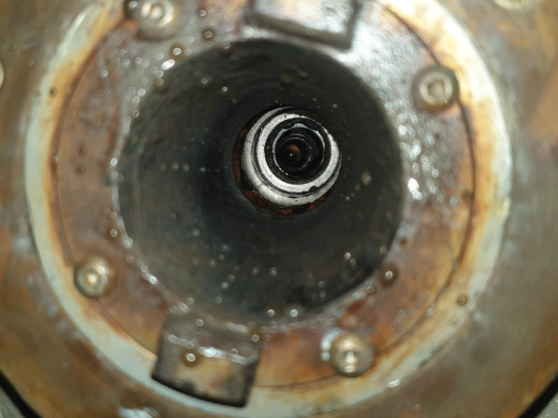
When the tool is locked, it would not go all the way up and stays around one millimetre lower. But in this case, actually was going almost all the way up, because of locking ball grooves made on the internal shaft wall.
start of Intermac JET spindle repair
We disassembled almost every part to machine the shaft internal slot and put a new pressed fit bush.

First, the pull nut is removed by a special HSD spanner according to the following drawing.

Spindle removal
This Intermac JET spindle repair started with spindle sensors, drain pipes, water connections and power cable disconnection.

The below photo shows sensors, drain, water and power cable removed.

After undoing the M8 bolts connections of spindle to its housing, it will be free to be removed. We moved Z axes all the way down and filled underneath it, then lifted Z axes up to gently take the spindle out.

HSD ES 710 spindle now is ready for repair.

Spindle disassembly
This Intermac JET spindle repair process started with top parts disassembly.
This non-contact very precise rotary joint for internal water, can be disconnected with undoing three M5 bolts on it.

The next part would be tool presence sensor disk. It does have two grub screws and usually a gear puller needed for removal.

The next part is rotary joint shaft as shown below. This precise part is left hand threaded.

The next part would be a pair of shaped holders for the spring puller shaft. Two M5 bolts to be used for holding this pair before loosening, other wise they would fall down.

After cap removal, the optical spindle speed sensor or encoder appears.

Needs to be very careful in removal and handling of its disk.

Next step would be the encoder reader holder removal.

By removal of six M5 bolts, the tool clamp spring and shaft would be freed.

For safe removal of this shaft needs to use longer M5 bolts and free spring pressure gently.

Spindle after encoder and clamp shaft removal shown in the following photo

Encoder cylindrical housing removed to reach the main stator and rotor.

At this pint in this Intermac JET spindle repair project, we reached the spindle’s rotor.

Spindle main electrical and power parts.

There is a temperature sensor in the spindle’s bottom housing, near the main bearings.

Measurement and making required bush
Very precise measurement of the existing shaft was required to make the correct bush for this Intermac JET spindle repair project.
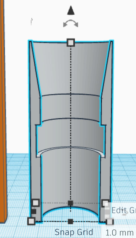
Tinkercad free 3D design app and web application has been used for part design.

We machined off inside of the spindle shaft to make enough room for required bush.
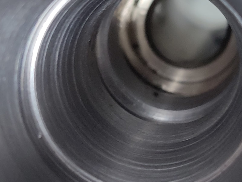
We insert the bush as demonstrated in the below photo for this Intermac JET spindle repair project.

Spindle parts assembly


Dear Sir.
I would like to inquire about the manufacturer and type of Spindle water rotary joint. Thank you in advance for your reply. greetings László Gila
Dear Gila
The rotary joint is an internal part of this spindle and made by HSD Company
Manufacturer won’t supply separate joint,
Regards
Ali