

In this post, we provide a comprehensive guide on Intermac JET spindle repair. The primary issue addressed here concerns the HSD ES 710 spindle, which exhibited a tool locking complication as a result of wear to the internal components of the shaft.
Related Spindle Repair Projects
Below is a list of other spindle repair projects successfully executed by PDMach:
- HSD ES369L Spindle Repair and Bearing Replacement
- Spindle Repair Project on INTERMAC MASTER 45
- Explore other previous projects on HSD INTERMAC CNC spindles showcased here, here, and here.
Diagnosis of the Spindle Issue
The issue was first observed in the tool presence sensor. The sensor detects the difference between a locked tool and an absent tool in the spindle through a spring puller shaft and a tool presence disk.
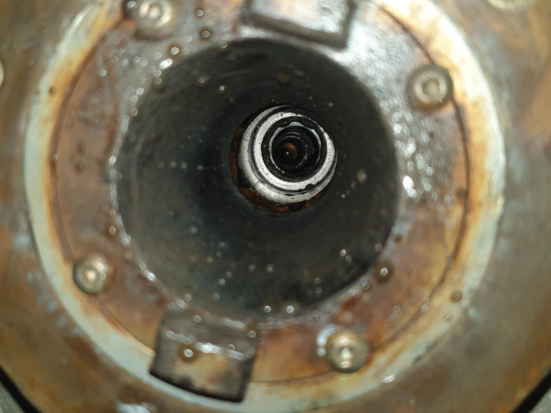
When the tool is locked, it should not rise completely but stay about one millimeter lower. However, in this case, it managed to rise close to the top due to the presence of locking ball grooves on the internal shaft wall.
Beginning of the Intermac JET Spindle Repair Process
To address the issue, we began by disassembling almost all components to machine the internal shaft slot and install a new pressed-fit bush.

Initially, the pull nut was removed utilizing a specialized HSD spanner, as illustrated in the accompanying diagram.

Removing the Spindle
This process began by disconnecting the spindle sensors, drain pipes, water connections, and power cables.

The photo below depicts the sensors, drain, water, and power cables after removal.

After detaching the M8 bolts that fasten the spindle to its housing, the spindle becomes free for removal. We lowered the Z-axis completely and added padding underneath, then gently lifted the Z-axis to take out the spindle.

The HSD ES 710 spindle is now prepared for the repair process.

Disassembling the Spindle
This process commenced with the disassembly of the top components of the Intermac JET Spindle.
The non-contact, highly precise rotary joint for internal water circulation can be disconnected by removing three M5 bolts.

Next, we would handle the tool presence sensor disk, which has two grub screws and generally requires a gear puller for removal.

Following this, we will focus on the rotary joint shaft, which is noted for its left-hand threading.

Next in line are the shaped holders for the spring puller shaft. To avoid them from falling, two M5 bolts must be used to secure this pair before loosening.

Upon cap removal, the optical spindle speed sensor or encoder will be readily visible.
Dear Sir.
I would like to inquire about the manufacturer and type of Spindle water rotary joint. Thank you in advance for your reply. greetings László Gila
Dear Gila
The rotary joint is an internal part of this spindle and made by HSD Company
Manufacturer won’t supply separate joint,
Regards
Ali